
Building Pedals
Moderated By: mods
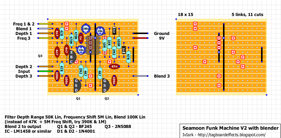
A few questions about this funk machine before I try rebuilding it:
From the following diagrams I'm assuming that:
1. The instruction "blend 2 to output" means that I should wire the middle lug from the blend pot to the bottom right of my switch?
2. That the instruction "Freq 1 & 2" beside the top left most yellow wire means that I should wire it to either of lug one or two on the pot and jumper lugs one and two together?


Shame. Was hoping I wasn't.
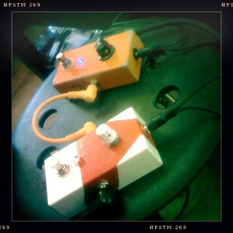
It looks to be wired up correctly. There are maybe one or two spots on the board that could maybe be tidied up. There's also that IC chip which is soldered straight to the board instead of being in a holstery yoke. Might have to have a look at those again, then maybe rebuild the board. I've spent more time wiring and rewiring than it would take to prepare a new one.
It looks to be wired up correctly. There are maybe one or two spots on the board that could maybe be tidied up. There's also that IC chip which is soldered straight to the board instead of being in a holstery yoke. Might have to have a look at those again, then maybe rebuild the board. I've spent more time wiring and rewiring than it would take to prepare a new one.
-
Concretebadger

- .

- Posts: 2111
- Joined: Sat Apr 14, 2012 5:29 pm
- Location: Leeds Leeds LEEDS
- Contact:
I'm not sure if it's of any help or whether it'll confuse you further, but I used this page as reference for the input/output and 9v jacks, plus the 3PDT switch. It was really clear and easy to follow, and the end results worked.
Best of luck with the Funk Machine...I'm going to do another Muff then try my hand at a Bee Baa after that.
Best of luck with the Funk Machine...I'm going to do another Muff then try my hand at a Bee Baa after that.
Rebuilt the board. Still doesn't work.
Might try rewiring again (again) tomorrow, perhaps using a different wiring guide to the one I've used successfully in other pedals.
It's weird. With the input jack connected to the enclosure, I get nothing at all out of it. If I remove the input jack from the enclosure so it's just floating around the place, I get buzzy noises.
-
Mike

- I like EL34s
- Posts: 39159
- Joined: Thu Apr 20, 2006 8:30 am
- Location: Edinburgh, Scotland
- Contact:
1. Yes wire lug 2 of the pot to the FX output lug of the switchBacchusPaul wrote:A few questions about this funk machine before I try rebuilding it:
From the following diagrams I'm assuming that:
1. The instruction "blend 2 to output" means that I should wire the middle lug from the blend pot to the bottom right of my switch?
2. That the instruction "Freq 1 & 2" beside the top left most yellow wire means that I should wire it to either of lug one or two on the pot and jumper lugs one and two together?
2. Wire to lug 2. you don't have to bridge 1 and 2 but ify ou wire to 1 the pot will just act as a fixed resistance.
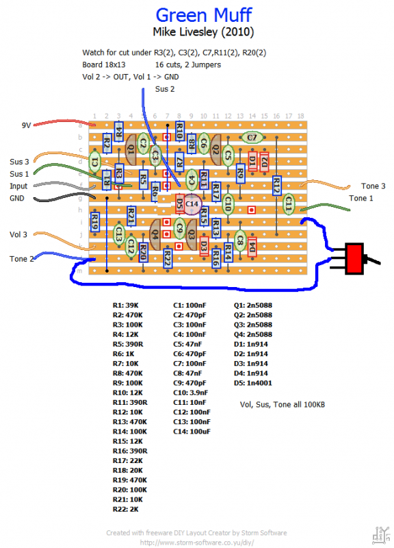
I've decided to give up on the Funk Machine and revisit it after I've had a few other successes (it's not very satisfying always having something not work). I've just finished building a Green Muff using hte diagram below and it works great. Now I want to add a Mid knob and a tone bypass switch.
So, (cross posting from another thread a bit here)
Mid Control
2: Would R2 and C1 on that mod description correspond to R2 and C1 on the Veroboard I've used?
Tone Control
How to do this?
http://www.muzique.com/lab/tbypass.htm
So, (cross posting from another thread a bit here)
Mid Control
1: I'm assuming that "22k to 25K potmeter" means that that's what the author is suggesting as a suitable range of values for the pot and that he doesn't meant something else, not somrthing else, like a 22k resistor in front of a 25k pot? Also, it doesn't matter which side of the pot I put the 1K resistor surely?BacchusPaul wrote:Sorry for the thread bump and the denseness, but how to do this? I need to order an extra 25k pot, a 22n cap and a 1k resistor?Mike wrote:No Big Muff is really middy, if you're building one definitely add a mid control as specified in the mod section - really great modification.
http://rkerkhof.ruhosting.nl/Taas/Mods/Big%20Muff.htmReplace C1 with a 22n cap
Replace R2 with a 22k to 25k potmeter (wired as a variable resistor) with a 1k resistor wired in series.
2: Would R2 and C1 on that mod description correspond to R2 and C1 on the Veroboard I've used?
Tone Control
How to do this?
http://www.muzique.com/lab/tbypass.htm
-
Mike
- I like EL34s
- Posts: 39159
- Joined: Thu Apr 20, 2006 8:30 am
- Location: Edinburgh, Scotland
- Contact:
1. Yes. Wire the pot as a variable resistor (use the wiper and ground lugs) between tone 3 and ground via a 1K resistor
Tone3 -> Mid2 (wiper)
Mid 1 -> 1K -> GND
2. No, look at this bit:
Green Russian version: R1=20k, C1=3.9n, R2=22k, C2=10n;
So in his example those are the values, so we're replacing R18 and C10 on my schematic.
Tone bypass is easier done by just taking the input to the tone control (junction of 20K/3.9nF or as we've seen R18/C10 = the track below the Tone 1 connection - this is your pre tone control signal. Wire this to one outer lug of an SPDT or SPST
Wire the common lug to the the tone 2 connection on the board
Switch made = tone bypass
switch unmade = tone as normal
Thanks Mike. I'd had a go at trying to work out what corresponded to what, but I'm glad I asked because I got it completely wrong. Looking at it again I can't even work out what I'd worked out previously. I think there's a limit to how much thinking I can do about electronics then it all completely turns to gibberish and I can't understand even the simple stuff.
So the tone bypass should look like this:
NB: I've accidentally removed R18 from this because I was going to try to combine the Mid control mod in the same diagram but then it stopped making sense to me so I stopped.
So the tone bypass should look like this:
NB: I've accidentally removed R18 from this because I was going to try to combine the Mid control mod in the same diagram but then it stopped making sense to me so I stopped.


Brilliant. B involves less messing around with the board. Should I leave R18 on the board as it is, then? I'm assuming that this mod removes it anyway?
Also, I know this is a really obvious one, but on the Tone Bypass mod, I can connect that common terminal to hole L3 on the board instead of L1 can't I? Might be a bit easier, just. Or can I connect it straight to the middle lug on the pot and leave the board alone altogether?
Also, I know this is a really obvious one, but on the Tone Bypass mod, I can connect that common terminal to hole L3 on the board instead of L1 can't I? Might be a bit easier, just. Or can I connect it straight to the middle lug on the pot and leave the board alone altogether?
Fixed!
Sounds THE FUCKING TITS.
It was perhaps the rookiest fault I can imagine making. I took out the mid knob and the tone switch and it still didn't work. I cleaned up anything that wasn't already very neat on the board and it still didn't work. Then I peaked inside the tape I'd wrapped around the resistor between the DC input and the LED and discovered that that wire had broken.
Put it all back together and it sounds immense. Pretty healthy volume increase with the mid bypass too.
THANKS MIKE!
I'm thinking it might be an idea to put a Saltbooster in this box as well and have the tone bypass be activated by the same switch as the saltbooster. My thinking is that it'd be a useful way of dialling in how much boost you want, or whether you want any at all, plus saltbooster pushing fuzz always sounds great.
I've read a bit about housing two pedals in one box and think I'm okay with that. The only thing I'm not sure about it whether I'd need a 4pdt switch so that I can switch the tone bypass on the same switch. There's no way around this, is there?
I've read a bit about housing two pedals in one box and think I'm okay with that. The only thing I'm not sure about it whether I'd need a 4pdt switch so that I can switch the tone bypass on the same switch. There's no way around this, is there?